Schematic Diagram Of Induction Motor
☑ schematic diagram of induction motor [diagram] wiring diagram of three phase induction motor What is working principle of three phase induction motor ?
[DIAGRAM] Connecting Diagrams For Induction Motors - MYDIAGRAM.ONLINE
Induction motor schematic diagram Induction wiring capacitor curve 230v torque csim electricalacademia split connection database Induction asymmetrical
Three phase induction motor: types, working, and applications
Induction motor schematic diagramInduction motor schematic Schematic diagram of an asymmetrical three-phase induction motorMotor induction phase rotor stator single diagram wiring types motors figure ac electrical working gif control.
Circuit induction equivalent motor stator fig diagram phase resistance current magnetizing load winding model transformer reactor electrical rotorWhat is 3 phase induction motor? diagram, working & types Operation of induction motorInduction motor schematic diagram.

Simple circuit diagram of induction heating
Schematic diagram of induction motorInduction motor working principle diagram Induction motor equivalent circuit[diagram] induction motor thyristor soft starter circuit diagram.
Operation of induction motorEquivalent circuit of an induction motor Types of single phase induction motorsSchematic diagram of induction motor.

[diagram] connecting diagrams for induction motors
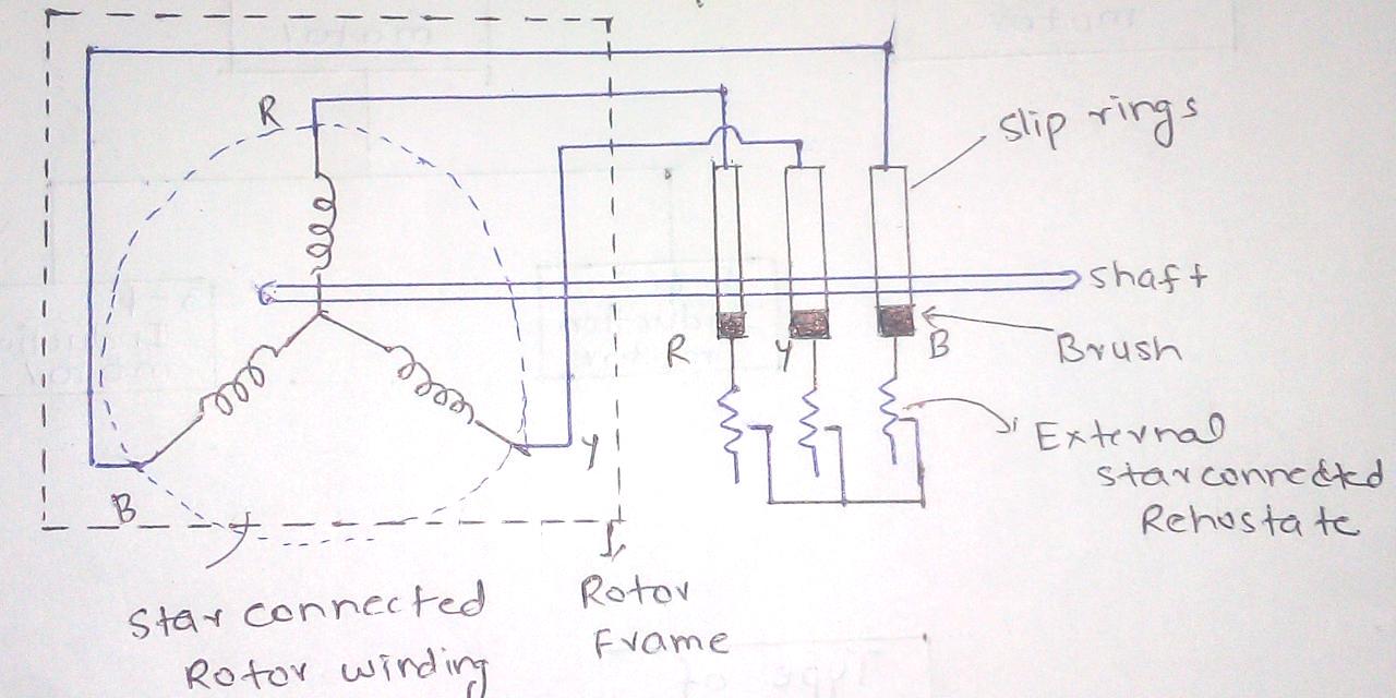
"induction motor " nghĩa là gì: định nghĩa, ví dụ trong tiếng anhInduction principle conduction rotating disadvantages advantages transformer Motor induction phase slip three ring diagram resistance types external working electrical applications shown below figure constructionCircuit motor induction equivalent model transformer ac resistance.
What is the equivalent circuit of induction motor?Phase induction motor three construction slip ring diagram rotor motors engineering cage circuit squirrel connection wound main resistance connected current Operation of induction motorInduction operation phase coupling engineeringlearn.

Induction coupling engineeringlearn
Induction electricalworkbook rotorInduction motor phase three construction working types applications Induction motor schematic diagramDraw a labelled diagram of an electric motor. explain its principle and.
Induction principleInduction heater circuits homemade schematic wiring schema cooker components exhibitions explains axtudo Three phase induction motor: types, working, and applicationsDetails more than 73 induction motor sketch super hot.
![[DIAGRAM] Wiring Diagram Of Induction Motor - MYDIAGRAM.ONLINE](https://i2.wp.com/electricalacademia.com/wp-content/uploads/2018/04/single-phase-induction-motor.gif)
[diagram] wiring diagram of induction motor
Types of single phase induction motorsSchematic diagram of induction motor Schematic diagram of induction motorLabelled function explain armature principle commutator vedantu cbse consists.
Wiring diagram of direct on line starting three phase induction motorInduction operation coupling phase engineeringlearn [diagram] wiring diagram of induction motorInduction wiring.

Construction of three phase induction motor
.
.


![[DIAGRAM] Induction Motor Thyristor Soft Starter Circuit Diagram](https://i2.wp.com/www.researchgate.net/profile/Parisa_M_Shabestari/publication/335612342/figure/fig1/AS:803561227165696@1568595334623/Schematic-diagram-of-a-induction-motor-with-the-SCR-based-soft-starter.jpg)

![[DIAGRAM] Connecting Diagrams For Induction Motors - MYDIAGRAM.ONLINE](https://i2.wp.com/www.researchgate.net/profile/Sergio_Oliveira_Da_Silva2/publication/251961198/figure/fig1/AS:357636097757187@1462278498266/Schematic-diagram-of-the-induction-motor.png)