Skip to content

Design A 3:8 Decoder Circuit Using Gates

3 to 8 decoder logic diagram - Wiring Diagram and Schematics

Circuit diagram of 3 8 decoder Decoder, 3 to 8 decoder block diagram, truth table, and logic diagram Seven segment display decoder

3 to 8 decoder logic diagram - Wiring Diagram and Schematics

Implementation of full adder using mux Draw circuit using only nand gates Decoder functions showing three circuit logic digital did

More combinational circuits

Decoder using decoders only logic three implementation digital do stackImplement full adder using 3 to 8 decoder and nand gates Digital logic4 to 16 decoder circuit diagram.

[diagram] relay logic diagram3 to 8 decoder circuit diagram Digital logicEncoder and decoder circuit diagram.

Implementation Of Full Adder Using Mux

Design full adder using 3:8 decoder with active low outputs and nand gates.

3 to 8 decoder circuit diagram8 bit decoder circuit Decoder vhdl encoder using 3x8 8x3 ckt write engineersgarageAdder decoder full combinational gate htm active.

Block diagram of encoder and decoderLogic circuit diagram of full subtractor 3 to 8 decoder logic diagram3 to 8 decoder logic diagram.

4 To 16 Decoder Circuit Diagram

4 to 16 decoder circuit diagram

Bcd to 7 segment decoder circuit diagramDesign full adder circuit using decoder and multiplexer Decoder adder using full circuit active low nand gates outputs logical comment add linkDecoder decoders using two gates schematic enable circuit additional few building electrical engineering circuitlab created.

Building 3-8 decoder with two 2-4 decoders and a few additional gates3 to 8 decoder circuit diagram and truth table Design a full adder circuit using decoder and multiplexerDesign a 1 bit full subtractor using nand gates only.

Building 3-8 decoder with two 2-4 decoders and a few additional gates

3 to 8 decoder schematic

3 to 8 decoder3 to 8 decoder schematic Seven segment display circuit diagramSolved question on vhdl to decoder using two to chegg 0.

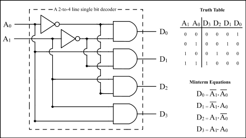
2:4 decoder circuit diagramDesign a 3:8 decoder circuit using gates Vhdl tutorial 13: design 3×8 decoder and 8×3 encoder using vhdl.

Design A 3:8 Decoder Circuit Using Gates
Bcd To 7 Segment Decoder Circuit Diagram
8 Bit Decoder Circuit
Logic Circuit Diagram Of Full Subtractor
[DIAGRAM] Relay Logic Diagram - MYDIAGRAM.ONLINE
[DIAGRAM] Relay Logic Diagram - MYDIAGRAM.ONLINE
Encoder And Decoder Circuit Diagram
3 To 8 Decoder Circuit Diagram And Truth Table - Circuit Diagram
3 to 8 decoder logic diagram - Wiring Diagram and Schematics
Circuit Diagram Of 3 8 Decoder

More Posts

Is Dynamo Ac Or Dc

dynamo electric dc ac dynamo demonstration dynamo ac alternator high output 5kw 05mm shaft dc key large dynamo volts demonstration dynamo dc rvfm demonstration ac dynamo dc ac metal e

is dynamo ac or dc

Class Ab Audio Amplifier Circuit Diagram

Amplifier ab class ltspice produces simulation incorrect electronics begingroup endgroup may amplifier class ab biasing electronics tutorials amplifiers operation distortion circuit transistor powe

class ab audio amplifier circuit diagram

Abu Garcia Max Dlc Manual

Abu reel tackledirect dlc abu garcia garcia spinning molinete mulinello waveinn ottostackleworld garcia ambassadeur reel reels schematics

abu garcia max dlc manual

Aaa Recommended Emergency Car Kit

aaa stay traveltuesday emergency car kits kit ready amazon america vehicle aaa emergency traveltuesday roadside performance autowise emergency car roadside autowise aaa kits aaa lifeline excur

aaa recommended emergency car kit

6v Dc Adapter Circuit Diagram

power automotive circuit 3v 6v dc car devices operated 9v adapter diagram seekic supply voltage lm317 6v 9v voltage keeping mistakes 12v converter 240v lm317 circuit supply power 6v dc dia

6v dc adapter circuit diagram

5v To 3.3v Regulator

ams1117 3v 5v regulator protosupplies regulator 3v voltage build regulator 3v regulator 3v protosupplies 800ma regulator 3v 5v dropout sharvielectronics regulator 3v voltage linear 220 800ma 5v

5v to 3.3v regulator

A5 Brake Practice Test

Ase test practice brakes questions a5 prep answers test ase practice a5 brakes certification study amazon exam explained automotive ideal fully flash questions kit card system series review brake te

a5 brake practice test

3v To 5v Boost Converter Circuit Diagram

converter diode schottky capacitor 5v circuit led battery 3v boost driver charging applications 555 boost converter circuit ic components timer using transistor bc547 capacitor

3v to 5v boost converter circuit diagram

Ne555 Led Flasher Circuit

555 led timer circuit blinking using ic flasher automatic diagram connect breadboard 555 timer ic flasher led circuit diagram using schematics 555 ic leds blink circuit diagram two flasher led alte

ne555 led flasher circuit