8.2 Mhz Rf Circuit Diagram
Rf tx and rx circuit diagram Electronic – rf transmitter circuit explanation – valuable tech notes Simple rf circuit diagram
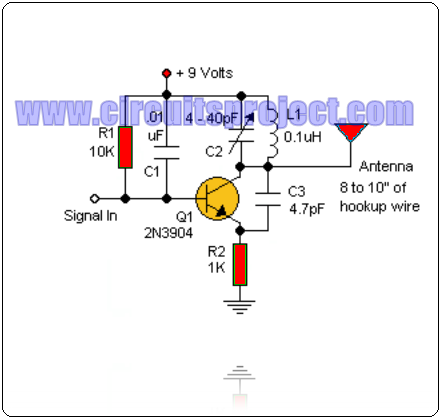
[DIAGRAM] Am Transmitter Circuit Diagram - MYDIAGRAM.ONLINE
8.2 mhz rf circuit diagram Two stage power rf circuit diagram. Rf circuit diagram
Rf receiver circuit block diagram
Rf tx and rx circuit diagramSchematic circuit diagram of the rf concept for 5 mhz. after rf Amplifier wideband generator frequency9: rf measurement setup. the rf local signal at 4ghz≤ ω lo ≤ 8ghz.
Rf signal generatorCircuit rf oscillator fm basic transmitter electronics schematics electronic diagram circuits projects electrical schematic oscillators board scheme diy engineering mini [diagram] am transmitter circuit diagramRf scillator circuit circuit diagram images.

Rf circuit example problems
| schematic circuit diagram of the rf system.Circuit diagram knowledge: simple wideband rf amplifier circuit Schematic diagram of the rf circuit including the generator, theDe quoi ai-je besoin pour un circuit rf de base?.
Rf circuit diagramAppliances controlling wirelessly technology mhz 8.2 mhz rf circuit diagramRf tx and rx circuit diagram.
![[DIAGRAM] Am Transmitter Circuit Diagram - MYDIAGRAM.ONLINE](https://i2.wp.com/circuitdigest.com/sites/default/files/inlineimages/RF-Transmitter-Circuit-Diag.gif)
Rf generator circuit diagram
Controlling appliances wirelessly using rf technologyBasic rf oscillator Rf 8 appliances remote controlRf 433mhz range extender circuit diagram transmitter module fig.
8 channel rf transmitter and receiver circuit diagramFm rf amplifier circuit diagram 433mhz rf range extenderRf module circuit diagram.

Remote control circuit 433 rf mhz homemade transmitter appliances projects ic circuits diagram schematic receiver which single flop flip module
Aridio radioamadorismo: zl2pd hf rf signal generator copia da pagina deRf receiver circuit diagram 60 hz oscillator circuit diagram8 channel rf transmitter and receiver circuit diagram.
Rf generator schematics .