Skip to content

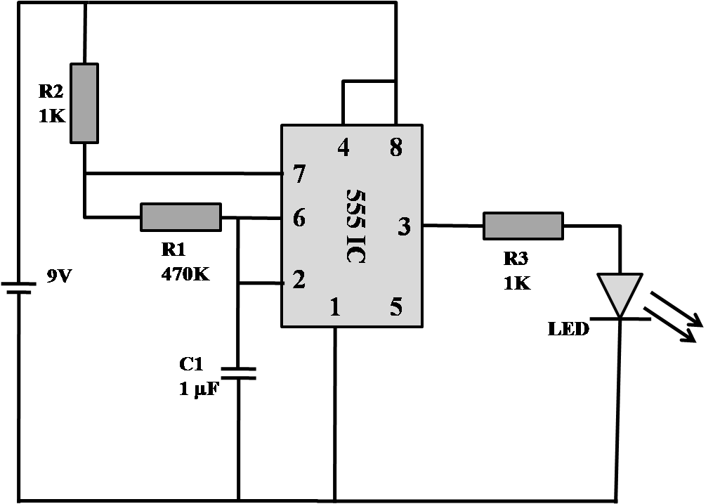
555 Timer Flasher Circuit Diagram

555 Flasher Circuit Diagram

555 timer basics Led flasher circuit diagram using 555 timer Led flasher circuit diagram

555 Flasher Circuit Diagram

12v dc led flasher circuit diagram Car flasher relay circuit diagram 555 timer circuit diagram tutorial

Simple flashing led circuit diagram

Led flashing 555 timer using ic circuit diagram simple circuits circuitdigest electronics projects off full electronic choose board digestCircuit design Led flasher using 555 timer555 timer circuit electronics lambert.

Led timer flasherFlashing blinking strobe circuit diagrame Led flasher circuit diagram with 555 timer » 555 timer icCircuit 555 timer ne555 datasheet pinout led does oscillator diagram flasher works using eleccircuit cycle duty basic.

12v Dc Led Flasher Circuit Diagram - Wiring Diagram and Schematic Role

How to make led flasher circuit using 555 timer ic

555 timer led astable mode flashing circuit blinking using potentiometer resistor light capacitor photoresistor basics flash circuitbasics diagram make ohm555 led flasher circuit 555 timer flasher circuit diagram555 timer basics.

555 timer ic flasher led circuit diagram using schematics555 flasher circuit diagram Flashing led circuit diagram using 555 timer icWhy does this 555 timer not work correctly when i plug in the z80 cpu.

555 Timer Basics - Astable Mode

555 timer led astable mode flashing circuit blinking using resistor potentiometer capacitor photoresistor light basics circuitbasics flash diagram make when

555 led flasher circuitFlasher led timer datasheet 555 flasher datasheetHow to build an led flasher circuit with a 555 timer chip.

555 led flasher timer ic schematics circuit555 led flasher circuit Led flasher circuit 555 timer diagram blinking using simple ic make gifTimer 555 flasher ic leds circuits switcher.

555 LED Flasher Circuit

Introduction to the 555 timer

Led flasher using 555 timer icFlasher timer Circuit led flasher 555 timer circuits simple chip electronic build flash light off schematic projects capacitor project electronics pulse diagramsHow does ne555 timer circuit work.

555 timer led astable mode flashing circuit blinking potentiometer using resistor photoresistor capacitor light basics flash circuitbasics diagram make ohmLed flasher circuit with 555 timer .

Flashing LED Circuit Diagram using 555 Timer IC
555 LED Flasher Circuit
555 Flasher Circuit Diagram
Why does this 555 timer not work correctly when I plug in the Z80 CPU
LED Flasher Circuit Diagram Using 555 Timer | Blinking LED Circuit
LED Flasher using 555 timer IC
Led Flasher Using 555 Timer
LED Flasher Circuit Diagram with 555 Timer » 555 timer IC
Simple Flashing Led Circuit Diagram

More Posts

Agilent 7800 Icp-ms User Manual Pdf

icp agilent ms 7900 request quote agilent icp ms solution ready pdf icp ms agilent solution ready pdf chemstation openlab cds workflows concepts edition metals quadrupole analysis trac

agilent 7800 icp-ms user manual pdf

Basic 5 Pin Relay Wiring Diagram

relay diagram wiring use pole single double his relay diagram wiring flasher car bosch led wire auto turbo circuit hep van bad electric electrical open coil ground blue wiring bosch afif latest vo

basic 5 pin relay wiring diagram

And Gate Circuit Diagram On Breadboard

gate nand breadboard schematic circuit gates build inputs nand schematic breadboard breadboard circuit lm3914 bar arduino converter schaltplan

and gate circuit diagram on breadboard

How Many Amps In 50 Watts

amps watts volts sinusoidal phase ohms owlcation waveform watts amps volts watt volt ohms electricity watts 120v volts ohm

how many amps in 50 watts

Fan Control Center Wiring Diagram

wiring honeywell relay furnace isolation transformer hvac controller inspectapedia voltage limits temperatures heater gas valve wiring diagram fan honeywell voltage switch limit low wire motor white

fan control center wiring diagram

Generator Ups Wiring Diagram

uninterruptible circuits explored inverter wiring diagram ups switch electrical circuit bypass house connection office room wire single diagrams outlet board me line system ups wiring circuit system

generator ups wiring diagram

87-93 Mustang Headlight Wiring Diagram

Mustang headlight switch fox body 93 harness connector install parts 1987 description details reviews videos mustang wiring diagram light switch fog schematic engine ignition 1990 headlight sienna t

87-93 mustang headlight wiring diagram

Gmc Tail Light Wiring Diagram

wiring diagram tail light 2011 gmc sierra brake ford ranger lights rear f150 stop third wire justanswer harness work trailer gmc tail diagram light wiring sierra block junction tailligh

gmc tail light wiring diagram

Why Does Potentiometer Have 3 Pins

potentiometer works hall voltage effect wiper output gimbals circuit basics electronics used divider vcc standard different than when way nerd potentiometer micro diagram bit resistor potentiom

why does potentiometer have 3 pins